Firmware architecture¶
How the Teensy firmware works, for anyone changing it. It runs on a Teensy 4.1 (i.MX RT1062, 600 MHz) and is built with PlatformIO and the Teensyduino core, but talks to the SPI, DMA and pin-mux hardware through its registers directly, because the Arduino SPI library cannot do what the sensor needs. Terms are explained in the glossary; the sensor's protocol in the SEIM reference.
uv run --group firmware python -m platformio run -d firmware              # build
uv run --group firmware python -m platformio run -d firmware -t upload    # build and flash
Files¶
| File | Role | Hardware-dependent? |
|---|---|---|
naneye_regs.h |
register model, frame geometry, exposure and clock maths | no — pure logic |
seim_unpack.h |
12-bit pixel-period extraction from 32-bit words | no — pure logic |
naneye_seim.cpp |
LPSPI3 + DMA driver, start-up, row lock, phase sequencer | yes: the part that talks to the sensor |
led_dac.cpp |
LTC2630 bit-bang | yes, simple |
usb_proto.cpp |
framing, CRC-32 | no |
main.cpp |
command interface, streaming loop, transmit pump | no |
watchdog.cpp |
RTWDOG hardware watchdog | yes, simple |
golden_vector.h |
GENERATED test vector, one real sensor row | no |
board.h |
pin assignment | — |
The split is deliberate: everything that can be reasoned about without a sensor is in the
pure-logic headers, and SELFTEST exercises them on the device. The hardware-facing part is
confined to one file.
The central idea: a phase sequencer¶
A frame is a deterministic sequence of clock counts (see frame structure). The sensor's state machine advances on the clocks we supply, so if we emit exactly the right number in each phase and flip the SDAT direction at the boundaries, we stay aligned by construction. There is no clock recovery and no PLL. There is exactly one search, at start-up (next section); after it, everything is counted.
Starting the sensor¶
seim::start() is the one place that cannot be pure counting:
- Power-cycle. The sensor needs a clean power-on reset, and the NanoBerry's rail takes
~630 ms to discharge, so
power(true)waits until the rail has been off at least 1 s. - The reference host's sequence: one activation clock,
CONFIG_0+CONFIG_1with idle set (bit-banged at ~1 MHz), one frame's worth of clocks with SDAT low, then both registers again with idle cleared and the rest of a 648-PP window of zeros. SDAT is then released. - Choose the sampling point on the training pattern now arriving (below).
- Presence check. The next received row must be mostly training pattern; if not,
STARTreports that no sensor is answering. - Row lock (
lock_row_phase()). How many clocks the first frame's training lasts varies slightly from start to start (measured: 12,074–12,084 bits, not a whole number of pixel periods), so the row timing is found. The firmware scans the received bits for row 1's 8 training words followed by pixel 0's start bit, clocks exactly the number of bits needed to reach the next row boundary, and checks that row starts with 8 training words. - Check 8 rows of real pixels of the first frame and report their bad words, then discard the rest of the frame, which is overexposed. Streaming starts at the next interface window.
Choosing the sampling point¶
Where in each bit the receiver samples decides whether the link works at all above
25 MHz. The sensor changes SDAT about 10 ns after the SCLK edge reaches it, and the edge
and the data both cross the wiring, so at 49.5 MHz, with 20 ns bits, rising-edge sampling
lands on the transition. LPSPI offers four sampling points per bit: TCR[CPHA] picks the
rising or falling edge (receive transfers only; register writes stay on CPHA 0, because the
sensor captures on the rising edge), and CFGR1[SAMPLE] adds one 10 ns clock of delay.
calibrate_sampling() runs straight after SDAT is released, when the sensor is sending
~12,000 bits of pure alternating training pattern: a known signal, and the hardest one for
the link. Each sampling point receives 1024 bits of it, the breaks in the alternation are
counted, and the point with the fewest wins (ties go to the rising edge, the reference
host's choice). Then, after the row lock, 8 rows of real pixel data are checked. It costs
about a third of the training, which is discarded anyway.
| SCLK | rising | falling | rising + delay | falling + delay | chosen |
|---|---|---|---|---|---|
| 12.375 MHz | 0 | 0 | 0 | 0 | rising |
| 24.75 MHz | 0 | 0 | 0 | 1022 | rising |
| 49.5 MHz | 1016 | 0 | 2 | 1020 | falling |
Breaks per 1023 bits of training, as START reports them on the bench.
CAL 0 turns calibration off (setting SAMPLE or PHASE by hand does too); CAL 1
turns it back on. tools/link_quality.py measures the word error rate at every sampling
point on pixel data, for when the answer needs checking.
The datasheet's shorter sequence (AN000611: a single idle-off write) was tried and removed. On this board it started only sometimes, and its counted phase left every row 2 clocks late; keeping a second start sequence that is known to be worse only invites someone to use it.
One frame, in steady state¶
Once locked, capture_frame() runs the same fixed sequence every frame:
capture_frame():
  INTERFACE    7776 clocks
                 24 bits   CONFIG_0 write          SDAT driven
                 24 bits   CONFIG_1 write          SDAT driven
                 7716 bits zeros, two frames       SDAT driven (keeps EMI off the line)
               [SDAT -> released, pulled down]
                 12 bits   last PP, received       the sensor's end-of-interface word
  SYNC+DELAY   (656 + rows_delay_pp) PP, clocked and discarded
  READOUT      320 x 3936 bits, DMA'd and unpacked
  EOF          8 PP, discarded
Note how cleanly the arithmetic lands: 648 PP = 7776 bits = 324 × 24 exactly, so a register write is a whole number of pixel periods; and SYNC+DELAY at minimum delay is 4 × 3936 bits, exactly four row-times.
The last pixel period is left to the sensor, which the datasheet says transmits an end-of-interface word there, and is received rather than discarded so bring-up can see whether it does. As a side effect SDAT is released a full PP before SYNC begins, so there is no overlap at the phase boundary at all. See SEIM reference for why this departs from AN000611.
The filler is driven as two maximum-size frames rather than 322 small ones. The sensor counts clocks, not time, so gaps inside the interface window do not break alignment — but wall-clock time spent there is time the pixels keep integrating, so 322 inter-frame gaps would stretch the real exposure beyond what the formula predicts.
Why one row per SPI frame¶
LPSPI supports frame sizes from 8 to 4096 bits (TCR[FRAMESZ]). A row is 328 PP = 3936
bits, which fits. That choice was the single most important one in the driver:
- The peripheral shifts 3936 bits without interruption, so "no clock gap within a row"
holds by construction rather than depending on
TCR[CONT]behaviour that cannot be verified without hardware. - Any inter-frame gap lands on a row boundary, which AN000611 says is the safe place, and which is where the three-pixel corruption does not occur.
- 3936 bits = 123 words of 32 bits exactly, and 3 words = 8 PP exactly, so the unpack is a fixed repeating pattern with no straddling special cases.
- One DMA arm and one
TCRwrite per row — 320 per frame, trivial — instead of per pixel.
The alternative (FRAMESZ = 12, one PP per frame) makes the unpack a one-liner but puts the
continuity of the clock at the mercy of FIFO scheduling. It remains the documented fallback
if the row-sized frame misbehaves.
Unpacking¶
The sensor sends MSB first and LPSPI (LSBF=0) places the first received bit in bit 31, so
a row is simply a big-endian bit stream:
static inline uint16_t pp_at(const uint32_t* w, uint32_t idx) {
    const uint32_t bit = idx * 12, wi = bit >> 5, off = bit & 31;
    const uint64_t acc = ((uint64_t)w[wi] << 32) | (uint64_t)w[wi + 1];
    return (acc >> (52u - off)) & 0xFFFu;
}
Row buffers carry one extra word of padding so w[wi + 1] is always readable — at
idx = 327 the read reaches word 123. That is what ROW_WORDS_PADDED is for.
host/naneye/decode.py::pp_at is the same function in Python, and
tests hold both to the golden row that SELFTEST uses on the device. The
two implementations cannot drift apart without a test failing.
Clocking¶
LPSPI root clock: CCM_CBCMR[LPSPI_CLK_SEL] = 3 (PLL2_PFD2, 396 MHz) with LPSPI_PODF = 3
(÷4) → 99 MHz. Then SCLK = 99 MHz / (SCKDIV + 2):
SCKDIV |
SCLK | Sensor mode | Error vs internal MCLK |
|---|---|---|---|
| 6 | 12.375 MHz | mclk_mode=2 |
+0.6 % |
| 2 | 24.750 MHz | mclk_mode=1 |
+0.2 % |
| 0 | 49.500 MHz | mclk_mode=0 |
+0.8 % |
99 MHz was chosen precisely because these three land within 1 %. The obvious 132 MHz root (PLL2 ÷ 4) would give 6–7 % errors, which costs dynamic range — the external clock must match the internal MCLK.
The gate must be off while CBCMR is written, and the change affects all LPSPI
instances. Only LPSPI3 is used here; the LED DAC is bit-banged specifically so no second
SPI peripheral is involved.
CCR[DBT] = 0 keeps the inter-frame gap as short as the peripheral allows, because that gap
is the row boundary.
SDAT direction¶
static inline void sdat_drive() { *portConfigRegister(PIN_SDAT_OUT) = s_mux_sdat; }
static inline void sdat_hiz()   { pinMode(PIN_SDAT_OUT, INPUT); }
SPI1.begin() does the pin muxing once at startup; the mux and pad control values for
SDO and SCK are cached, so the direction flip and the hand-back after bit-banging are single
register writes. The pad registers matter because pinMode() overwrites drive strength and
slew, which at 49.5 MHz is not something to leave to chance.
Bit-banging exists because LPSPI cannot produce frames shorter than 8 bits, and the start-up sequence needs exactly 1 activation clock and then 10 alignment clocks. The reference host bit-banged these too.
The alignment clocks must not drive SDAT
bitbang_clocks() takes an explicit drive_sdat flag. The activation clock is sent
with SDAT driven low, as the reference host does. The 10 alignment clocks are not:
they come after idle mode is cleared, by which point the sensor has entered INITIAL
PRE-SYNC and is driving SDAT itself. Driving it then is bus contention, and the
datasheet makes releasing the upstream driver before the sensor transmits the host's
responsibility. This was a real bug, found in review rather than on hardware.
Buffering and the rule that must not be broken¶
The capture loop owns the sensor link and must never block on USB.
A stalled host would cost sensor synchronisation, which is far more expensive than a lost frame. So:
- Two 128,000-byte frame buffers in
DMAMEM(OCRAM), enough for packed 10-bit. - Capture fills one while the other is transmitted.
- Transmission happens in
tx_pump(), which writes only what the USB endpoint has room for right now and is called from the row gaps via theIdleFncallback — ~159 µs of idle CPU per row at 24.75 MHz, against a few hundred cycles of unpacking. - If a frame is still in flight when the next completes, the new frame is dropped whole and counted. A frame is never truncated.
raw12 (209,920 bytes) borrows the whole region and so runs single-buffered; the loop waits
for the transmit to finish before capturing over it. It is a diagnostic format, not a
streaming one.
Memory, measured at link time: RAM2 269,408 bytes used of 524,288; RAM1 has 447 KB free for locals. PSRAM is not required — row-chunked capture rather than whole-frame DMA is what makes that true.
Error handling¶
In layers, because SEIM itself carries almost no redundancy: each 12-bit word has a start bit that must be 1 and a stop bit that must be 0, each row starts with 8 known training words, and that is all. No checksum, no ECC.
- Avoid errors. The sampling point is measured at every start, above. At the chosen point the link has run 60 s at 49.5 MHz (220 million pixel words) without a single broken word.
- Detect them. Every row is validated: 8 training words, and start and stop bits on
all 320 pixel words. Rows with any error count in the header's
rows_failed. If the training words fail, the row phase itself is in doubt and the frame is flaggedSYNC_LOST. - Conceal what gets through. A pixel word with broken framing is known to be wrong,
so
extract_row()replaces its value with the mean of the nearest intact pixels on the same row, and counts it inpixels_concealed(flagCONCEALED). A row with more than 32 broken words is lost rather than damaged and is not concealed. Anything that would rather have the bad pixels than an estimate of them has the count in the header and can discard the frame. - Recover. A capture that fails outright (the hardware stops responding) triggers a full re-start, which power-cycles the sensor. If the firmware itself hangs, the watchdog resets the Teensy.
What cannot be done: an error in one of a word's ten data bits leaves its framing intact, so it cannot be detected, let alone corrected. The defence against those is layer 1.
Layers 2 and 3 were measured with a fault-injection hook, since removed, that corrupted n random pixel words per frame after they were received: start bit knocked out, data scrambled, as a real bit error looks. With 500 per frame at 49.5 MHz, every one was detected and concealed:
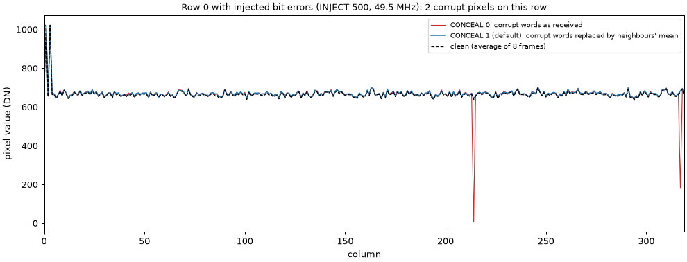
| 500 corrupt words per frame | mean |difference| from a clean frame | pixels more than 100 DN off |
|---|---|---|
| left as received | 3.64 DN | 416 |
| concealed | 2.08 DN, against 1.80 DN of ordinary frame-to-frame noise | 3 |
SELFTEST checks concealment too, on the golden row with one word broken on purpose.
When the row lock misses¶
Locking has one chance per power-on: it has to catch the moment the first frame's training
turns into pixels, in a single pass. Three things make that survivable. The search covers 48
rows, because how long the training lasts is a property of the module and not a constant. A
candidate that fails its check is stepped over rather than fatal. And START will
power-cycle and try the whole sequence up to three times before it reports no sensor. The
START ok reply says which attempt won and how many false candidates it passed, so a start
that needed help says so instead of looking identical to one that did not.
Telling the firmware which sensor is fitted¶
A mono and a colour NanEyeC are indistinguishable on the link, so CFA MONO|BGGR|GBRG|GRBG|RGGB
tells the firmware which is on the board. It keeps the answer in EEPROM, so it survives
resets and reflashes, reports it in ID, and puts it in bits 4–6 of every frame header's
flags. Nothing else in the firmware cares: the pixels are passed through untouched, and all
the colour work happens on the PC.
Register writes land one frame late¶
Measured. The frame header therefore reports the configuration that was in force for that frame, not the most recently written values — otherwise a recording's metadata would be silently wrong by one frame, which for measurement work is worse than useless.
Commands¶
Plain ASCII lines in, always-framed packets out (spec.md §7). Full list in
main.cpp::handle_command and the host page.
Commands are polled between frames, not during one, because capture_frame() owns the CPU
for the whole readout. So expect up to one frame period of latency — ~52 ms at 24.75 MHz,
~104 ms at 12.375 MHz. That is deliberate: handling START, STOP or PROBE halfway
through a readout would re-enter the driver underneath itself.
Diagnostics¶
Kept in the shipping firmware on purpose: these are what found the faults that hid first
light (see Hardware: first light). None of
them is needed for normal streaming. All except ID and SELFTEST need streaming stopped.
| Command | What it does | Use it when |
|---|---|---|
ID |
Firmware version, actual SCLK (derived from the clock registers, not assumed), registers, format, and last reset cause (normal / WATCHDOG) |
Always first. A WATCHDOG right after flashing is normal; see below |
SELFTEST |
Unpack and exposure maths against the embedded golden row | Separating decode bugs from link bugs |
PROBE [rows] |
A phase-correct frame cycle reporting word statistics instead of an image | Checking an already-running link without disturbing its phase |
LISTEN [rows] |
Clocks up to 2000 rows with SDAT released and classifies each one: . zeros, A 0xAAA, S 0x555, P pixels, ? mixed. Prints a run-length map, e.g. Ax3 Px320 ? . Sx4 Px320 |
Finding out what the sensor is doing, with no assumptions about phase. Never drives SDAT, so it is always safe |
START REF [VERBATIM] [FAST] [EARLY] [FIRST] [rows] |
The reference host's start sequence, then (with rows) a gapless LISTEN. VERBATIM uses the reference's exact register values, FAST sends the first write pair at SCLK rate instead of bit-banged, EARLY releases SDAT straight after the idle-off write, FIRST stops after the idle-on pair |
Bisecting a start-up that does not start |
CAL 0 / CAL 1 |
Sampling-point calibration at START off or on (default on) |
Forcing a sampling point for an experiment |
SAMPLE 0 / 1, PHASE 0 / 1 |
Sampling point by hand: delayed or not, rising or falling edge. Turns calibration off | With tools/link_quality.py |
HYS 0 / HYS 1 |
Schmitt-trigger input on the receive pin | Slow or noisy edges (made no difference on the bench) |
Host-side companions, all driving the Saleae through its MCP server:
tools/show_bringup.py: triggers on NanEye_EN, runs a start command, and plots an overview plus zooms of the idle-off write, the sensor's first output, and its launch delay.tools/check_alignment.py: where each row transfer lands relative to the sensor's own row starts. Every burst at the same offset, and that offset −96, means phase-locked.tools/capture_link.py/tools/analyze_link.py: general capture and link checks (clock rate, exact phase counts, register writes).
Watchdog¶
RTWDOG (WDOG3), 2 s timeout on the 32 kHz LPO clock (watchdog.cpp). Fed from loop(),
per row in LISTEN, and while power(true) waits out the sensor's power-off time. The
longest legitimate blocking operation is about 0.7 s. After a reset the USB port
re-enumerates in about 0.3 s and ID reports it. Flashing usually leaves last reset:
WATCHDOG too: the old image parks in the bootloader hand-off with the watchdog running.
That is harmless.
Known risks¶
The design record carries the full list. Where the risks identified before bring-up ended up:
| Risk | Outcome |
|---|---|
A bare TCR write with TXMSK=1 might not start a receive-only frame |
Works: every row is received this way |
| SDAT might not be released fast enough at the INTERFACE→SYNC boundary | Works: the sensor owns the last pixel period of the window, so there is a full PP of margin |
Clock accounting in start() must agree with the sensor to the bit |
It could not, because the first frame's length varies. Replaced by the row lock |
| Signal integrity above 24.75 MHz on flying leads | 49.5 MHz first failed, and the cause was first misread as slow edges. It was the sampling point, now measured at every start; 49.5 MHz runs clean on jumper wires |
| Not foreseen: DMA buffers in cached memory | Found and fixed: the cache is invalidated around every row transfer |